Scratch & Dig Measurement—
A Simple Requirement with Complex Challenges
Historically, scratch and dig inspection has remained one of the more challenging and subjective specifications in optical manufacturing. Parts are typically evaluated by trained inspectors who compare observed defects against physical reference standards under controlled lighting conditions.
While scratch and dig requirements are sometimes treated as cosmetic criteria, surface defects can have significant performance implications. Scratches and digs may contribute to stray light, image artifacts, localized transmission losses, reduced coating durability, crack initiation and propagation, increased laser absorption, and other optical or mechanical failures.
Automated measurement systems began emerging in the early 2000s, including pioneering instruments developed by Savvy Optics. By leveraging digital imaging, these systems introduced greater traceability, repeatability, and consistency than traditional visual inspection methods, while enabling more precise characterization of defect geometry.
Despite decades of development, fully automated scratch and dig measurement remains an elusive goal. Many available systems are expensive, limiting adoption across the broader optics ecosystem and creating barriers for both manufacturers and end users seeking objective, repeatable measurements.
At first glance, scratch and dig measurement appears straightforward: acquire an image, identify defects, and measure them. In practice, however, it is a remarkably complex image-processing problem. Variations in illumination, defect morphology, surface shape, and interpretation criteria make robust automation difficult.
GeoPulse addresses these challenges through a combination of specialized hardware, intelligent acquisition routines, and advanced analysis software within the MODI platform.A Simple Requirement with Complex Challenges
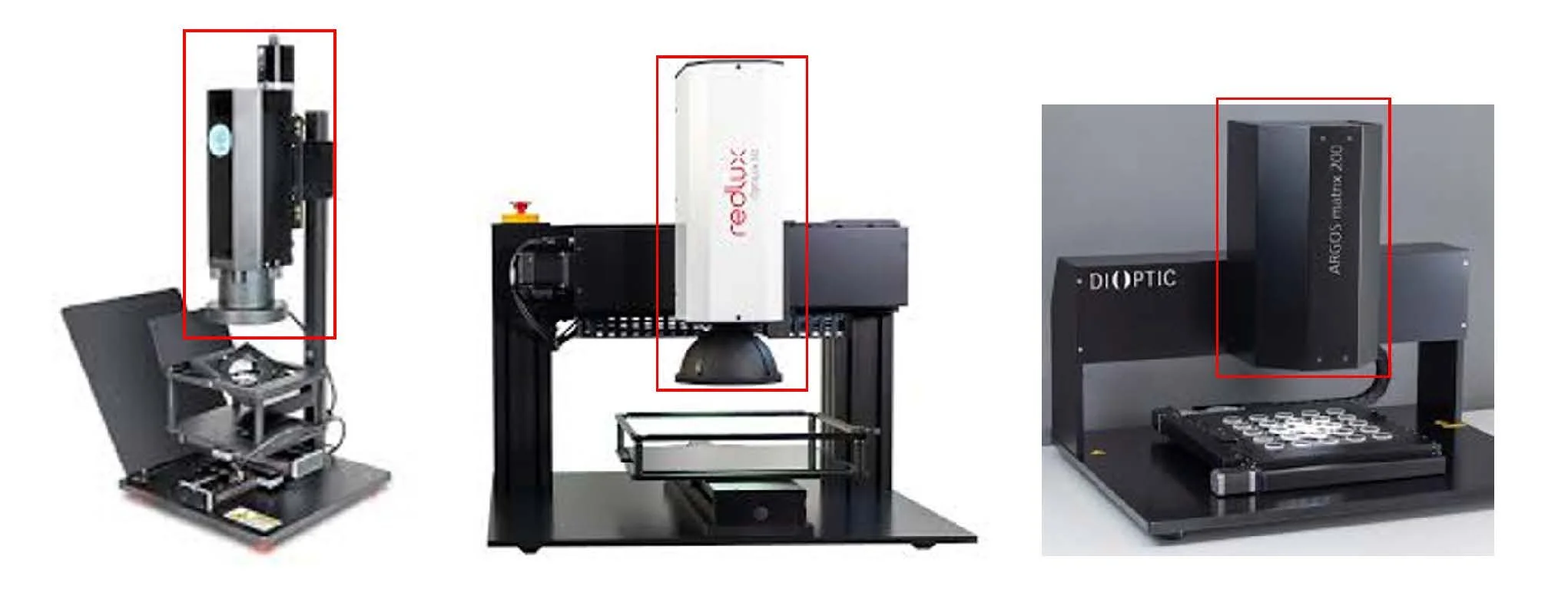
Figure 1—Alternative measurement devices exhibiting similar architecture - a single sensor with bulky optics. Generally, includes lighting, gantry, and a high-resolution camera.
Alternative devices for scratch dig measurement largely rely on a single-camera architecture with fixed optics and illumination. This design requires tradeoffs between field of view, resolution, defect sensitivity, and throughput, ultimately limiting the range of workflows and measurement capabilities that can be supported within a single platform.
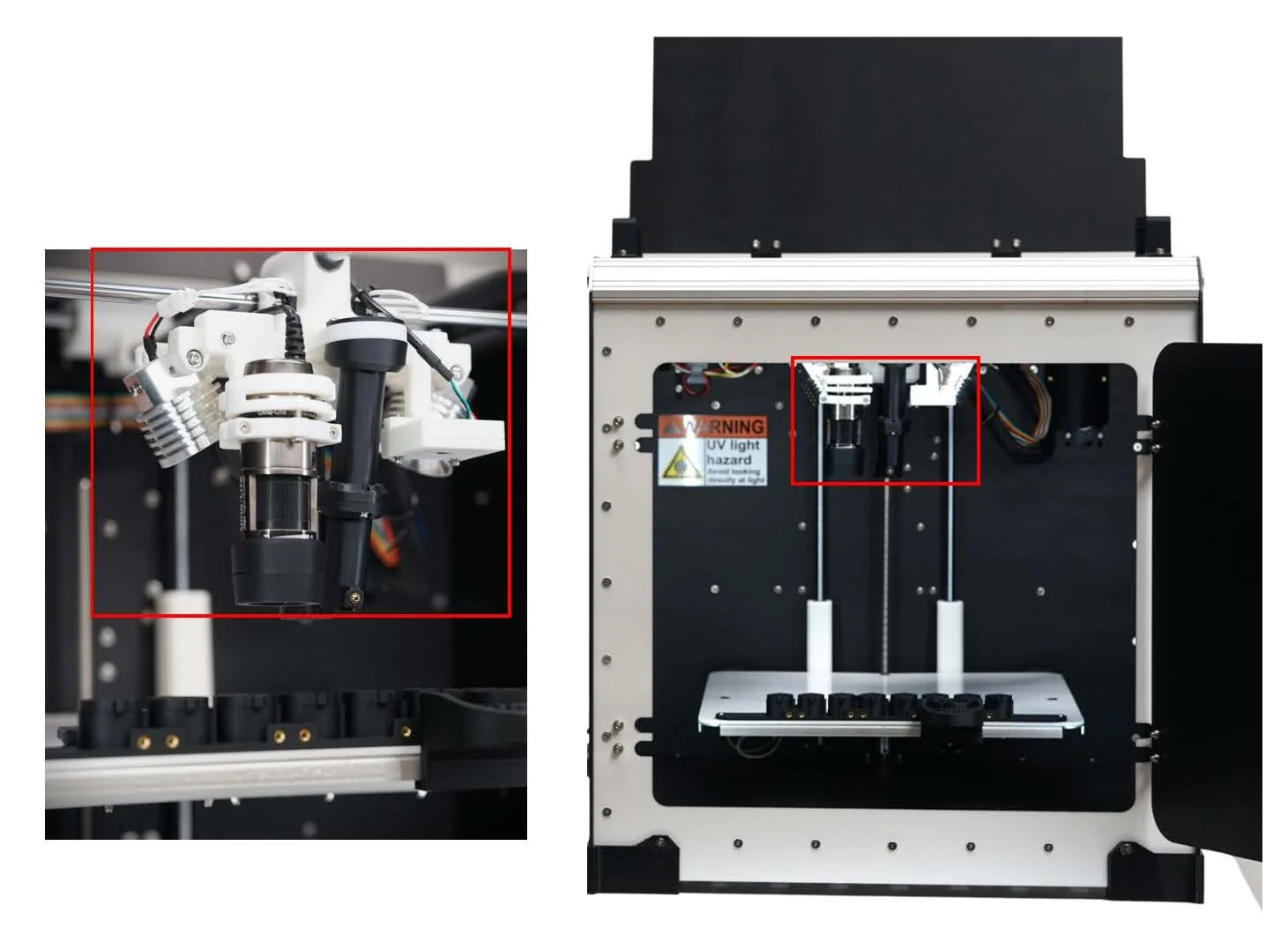
Figure 2—The MODI system by GeoPulse: self-enclosed, self-calibrating system with adaptable multi-sensor optical head and context camera.
The MODI system by GeoPulse combines a self-enclosed, self-calibrating platform with a modular multi-sensor optical head and context-camera-assisted automation for flexible inspection and measurement workflows.
A variety of illumination modes enable dynamic imaging and intelligent inspection workflows, including automatic glare detection and compensation, with support for ring, coaxial, darkfield, scatter, multi-angle, and backlighting modes.
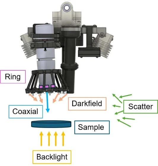
Figure 3—Various lighting methods allowing for dynamic imaging and smart illumination workflows
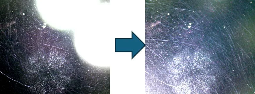
Figure 4—Glare detection and auto-adjustment workflow
Our advantage:
HARDWARE: Unique hardware solutions – long working distance microscopy and versatile illumination
ROUTINES: Smart routines including auto-lighting selection
SOFTWARE: Robust algorithmic pipeline for pre-processing, stitching & classification
Complementing the hardware platform and intelligent imaging routines, our software utilizes sophisticated multi-stage iterative algorithms to measure defects with high accuracy and repeatability. This includes more nuanced
These methods have been validated against some of the most demanding industry standards and inspection requirements.
Micros Scratch & Dig Target
MOTP-ISO Scratch-Dig Panel, ISO 10110-7 Standard
Lithography defects down to 5um scratch and 50um dig
ADDITIONAL CONTENT: Photos and Conclusion?